Scaling
As you start adding more resources to your configuration a few problems can arise:
- The Terraform state file becomes bigger and making changes with Terraform takes much longer.
- A single shared statefile is a risk. Making a change in a Development tenant could have implications to a Production tenant.
- No ability to run changes in parallel. Only one concurrent plan may run at any given time as the statefile is locked during the operation.
These problems are not unique to Network as Code and would occur when scaling any Terraform resources using a single state file. To address these problems users have to consider distributing state. For more information about Terraform state see: https://developer.hashicorp.com/terraform/language/state.
In this section on scaling, we will cover how to deal with those problems using two different approaches. The basics of distributing state will be covered first, followed by generic examples on how GitLab and Terraform Cloud can be used to create separate workspaces.
Understanding state distribution
Section titled “Understanding state distribution”In the examples shown on this site, you may have noticed that there is a single Terraform plan (main.tf) file in the example repositories. Executing this plan therefore results in a single Terraform state file. The module combines all the *.yaml files found in the data folder, followed by passing the content to the different terraform modules. This could lead to potentially thousands of resources in larger environments. But what if we did not pass all of the content to the modules? That logic would allow us to create different plans, which could focus on a specific section of the configuration. To understand that better, consider the following example in main.tf:
</snip>module "aci" {  source  = "netascode/nac-aci/aci"  version = "1.0.0"
  yaml_directories = ["data"]
  manage_tenants            = true}
Also consider two large tenant definitions in the data folder. (containing 100 BDs, 100 EPGs and 4 static path bindings per EPG) running terraform plan results in the following output:
terraform plan</snip>Plan: 2010 to add, 0 to change, 0 to destroy.All files in the data/ folder ending in *.yaml are merged together and passed as data to the tenant module. The module has a for_each loop that looks through the combined data to find all tenant definitions. The output of a terraform plan or apply resulted in 2010 changes. If the objective is to split Terraform state files, you could consider the following example for two tenants:
Directorydata
- tenant_TEN1.nac.yaml
- tenant_TEN2.nac.yaml
Directorydefaults
- defaults.nac.yaml
Directorymodules
- modules.nac.yaml
Directoryworkspaces
Directorytenant_TEN1
- main.tf
Directorytenant_TEN2
- main.tf
The data folder is left intact in the directory structure above. But instead of having a single main.tf plan in the directory root, multiple main.tf plans have been created by the user, each in a different directory. In this example, the data for tenant TEN1 is passed to the tenant module in workspaces/tenant_TEN1/main.tf and tenant TEN2 to workspaces/tenant_TEN2/main.tf. This would result in two different local state files in each workspace directory, one for each tenant:
</snip>module "aci" {  source  = "netascode/nac-aci/aci"  version = "1.0.0"
  yaml_directories = ["../../data"]
manage_tenants = true managed_tenants = ["TEN1"]}</snip>module "aci" { source = "netascode/nac-aci/aci" version = "1.0.0"
yaml_directories = ["../../data"]
manage_tenants = true managed_tenants = ["TEN2"]}In this example, a lookup is done for tenant.name == TEN1 and TEN2, respectively. Only the matching data is passed to the module.
Running terraform plan in each workspace will now result in the following:
~/workspaces/tenant_TEN1 > terraform plan</snip>Plan: 1005 to add, 0 to change, 0 to destroy.
and~/workspaces/tenant_TEN2 > terraform plan</snip>Plan: 1005 to add, 0 to change, 0 to destroy.
Running terraform apply will result in two different state files, one for tenant TEN1 and one for tenant TEN2. This allows executing both plans in parallel, reduces the risk associated with a single statefile, and speeds up the execution.
Alternatively you could also create multiple data directories, or even distribute the directories containing the *.yaml files in multiple repositories. Here is an example of the structure:
Directorydata
Directorytenant_100-130
- tenant_100.yaml
- tenant_101.yaml
- …
- tenant_130.yaml
Directorytenant_131-160
- tenant_131.yaml
- tenant_132.yaml
- …
- tenant_160.yaml
- defaults
- defaults.yaml
Directoryworkspaces
Directorytenant_100-130
- main.tf
Directorytenant_131-160
- main.tf
The workspaces/node100-130/main.tf would look like this:
module "aci" {  source  = "netascode/nac-aci/aci"  version = "1.0.0"  yaml_directories = ["../../data/tenant_100-130"]
  manage_tenants            = true}
It is possible to go more granular and select specific yaml files. Instead of using yaml_directories it is possible to make use of yaml_files.
module "aci" {  source  = "netascode/nac-aci/aci"  version = "1.0.0"
  yaml_files = ["../../data/tenant_101.yaml","../../data/tenant_102.yaml"]
  manage_interface_policies            = true}
Be mindful of the object hierarchy in ACI when splitting state even further. Consider the following example:
cat tenant_a_vrf_a.yaml---apic:  tenants:    - name: tenant-a      vrfs:        - name: vrf-a
cat tenant_a_vrf_b.yaml---apic:  tenants:    - name: tenant-a      vrfs:        - name: vrf-b
The plans both have tenant-a listed as a resource. When using different workspaces (plans) for each tenant_a_vrf_*.yaml, the result of executing terraform apply would be tenant-a that contains both vrf-a and vrf-b. However, changes in one of the tenant_a_vrf_*.yaml files, or a terraform destroy could result in removal of tenant-a, as this resource is part of the terraform statefile. Terraform expects a one-to-one mapping between configured resources instances and remote objects. Referencing the same object from multiple *.yaml files is therefore strongly discouraged.
However, if you wish to split state like this, you can make use of the managed flag in the tenant definition file to indicate whether a tenant should be created/modified/deleted or is assumed to exist already and acts as a container for other objects.
The below yaml file would assume the tenant to already exist. It would remain untouched by Terraform operations:
cat tenant_a_vrf_b.yaml---apic: tenants: - name: tenant-a managed: false vrfs: - name: vrf-bUsing Gitlab
Section titled “Using Gitlab”This section assumes that you are reasonably familiar with Gitlab operations. For more information including an extensive example on how to use Network as Code with Gitlab, please visit the CI/CD Example on this site. That section covers setting up projects, creating runners and more.
In the understanding the basics of state distribution, there was a single data directory that contained all *.yaml files with the intended configuration. Two separate directories were then used to create two separate plans, in order to distribute state. The same logic can be used when using Gitlab. An example of how to do this for two tenants is explained below.
Create a new project to store the intended configuration:
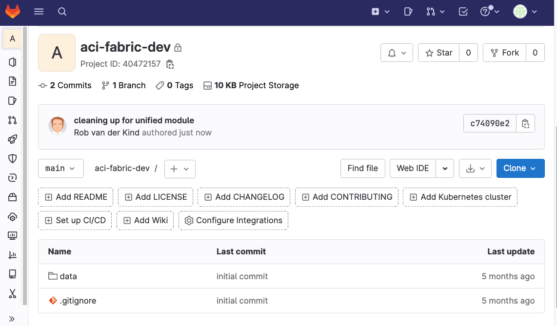
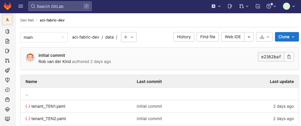
The data folder still contains all *.yaml files (this example only has two tenants):
Set up two additional projects. One for each tenant:
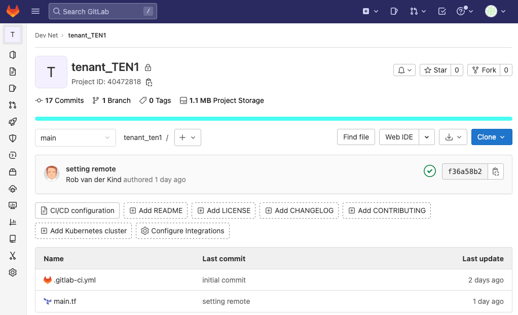
You are also required to register a Gitlab runner for each new project.
The main.tf plan for tenant TEN1 is the following:
terraform {  required_providers {    aci = {      source = "CiscoDevNet/aci"    }  }  backend "http" {  }}
provider "aci" {}
variable "data_repo" {  default = "aci-fabric-dev"}
module "aci" {  source  = "netascode/nac-aci/aci"  version = "0.7.0"
  yaml_directories = ["${var.data_repo}/data"]
  manage_tenants = true  managed_tenants = ["TEN1"]}
The main.tf plan for tenant TEN2 is the following:
terraform {  required_providers {    aci = {      source = "CiscoDevNet/aci"    }  }  backend "http" {  }}
provider "aci" {}
variable "data_repo" {  default = "aci-fabric-dev"}
module "aci" {  source  = "netascode/nac-aci/aci"  version = "0.7.0"
  yaml_directories = ["${var.data_repo}/data"]
  manage_tenants = true  managed_tenants = ["TEN2"]}
The example gitlab-ci.yml pipeline file is the same for both projects:
include:  - template: Terraform/Base.gitlab-ci.yml  # https://gitlab.com/gitlab-org/gitlab/blob/master/lib/gitlab/ci/templates/Terraform/Base.gitlab-ci.yml
image:  name: "$CI_TEMPLATE_REGISTRY_HOST/gitlab-org/terraform-images/releases/1.3:v0.47.0"
variables:  TF_ADDRESS: ${CI_API_V4_URL}/projects/${CI_PROJECT_ID}/terraform/state/${CI_PROJECT_NAME}
stages:  - validate  - test  - build  - deploy  - cleanup

.before_script_template: &clone  before_script:    - cd "${TF_ROOT}"    - git clone https://gitlab-ci-token:${CI_JOB_TOKEN}@gitlab.com/YOUR_ORG/YOUR_REPO
fmt:  extends: .terraform:fmt  dependencies:
validate:  extends: .terraform:validate  <<: *clone
build:  extends: .terraform:build  <<: *clone
deploy:  extends: .terraform:deploy  <<: *clone  dependencies:    - build
cleanup: extends: .terraform:destroy <<: *clone dependencies: - deployWhen a pipeline is about to run, GitLab generates a unique token and injects it as the CI_JOB_TOKEN variable. This token can be used to authenticate and clone another repository, as long as the token has the right permissions. Each plan only partially passes the data (matching the filters of managed_tenants) to the Network as Code ACI module. Each pipeline will therefore only run against a single tenant. This allows you to work against each tenant in parallel in different workspaces.
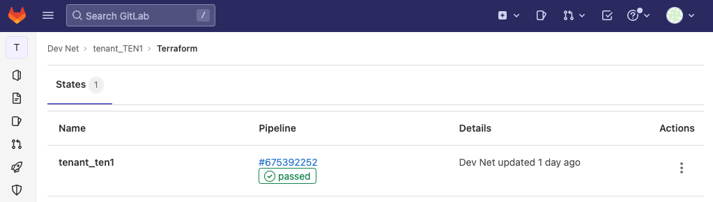
Each project will have its own Terraform state:
Using Terraform Cloud for Business
Section titled “Using Terraform Cloud for Business”Terraform Cloud is HashiCorps managed service offering. It manages Terraform runs in a consistent and reliable environment, and includes easy access to shared state and secret data, and access controls for approving changes to infrastructure. Terraform Cloud is available as hosted service at https://app.terraform.io. HashiCorp offers different tiers to consume their features. For more information on pricing, see https://cloud.hashicorp.com/products/terraform/pricing. This section requires access to the Terraform Cloud Business tier as self-hosted agents are a requirement to deploy configuration, as it is unlikely that the Application Policy Infrastructure Controller (APIC)s are exposed to internet. Therefore a local agent is used to execute the Terraform actions.
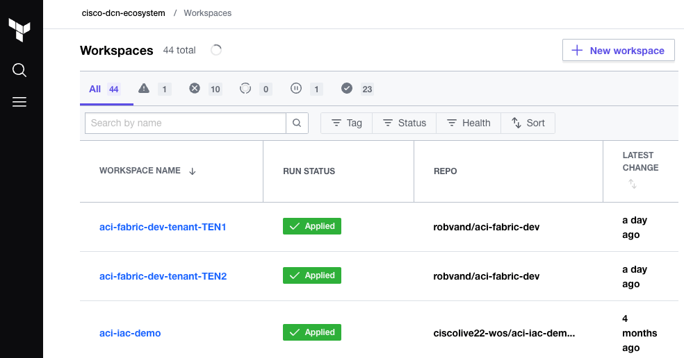
Terraform Cloud manages infrastructure collections with workspaces instead of directories. A workspace contains everything Terraform needs to manage a given collection of infrastructure. Separate workspaces function like completely separate working directories on your local machine. From a workspace you have the option to watch a git repository and start a new run based on any changes. You could consolidate all your plans and configuration (defined in *.yaml files) in a single repository and automatically queue and run the plan, from a single workspace. This section however focusses on how to distribute state and explain how to do that using multiple workspaces. HashiCorp recommends breaking down large monolithic Terraform configurations into smaller ones. Workspaces can be created through the Workspaces API, Terraform Cloud CLI or via the GUI. This section will show how to set up multiple workspaces to distribute state.
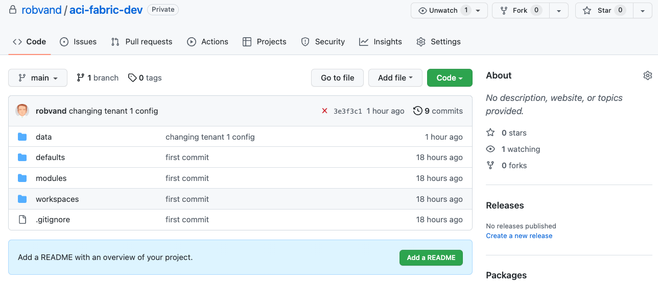
A single git repository is used as we can reference this from multiple workspaces. The structure is the same as what was shown in the introduction section of this page. Both the *.yaml files and the plans for each workspace are included in the same git repository. The example below uses github, but Terraform Cloud also supports integration with other version control systems. The directory below has been synced to a github repository:
Directorydata
- tenant_TEN1.yaml
- tenant_TEN2.yaml
Directorydefaults
- defaults.yaml
Directoryworkspaces
Directorytenant_TEN1
- main.tf
Directorytenant_TEN2
- main.tf
Same directory in github:
Each folder within the workspaces directory will get its own workspace in Terraform Cloud. In the workspace click new workspace to add a new workspace:
Create a new workspace:
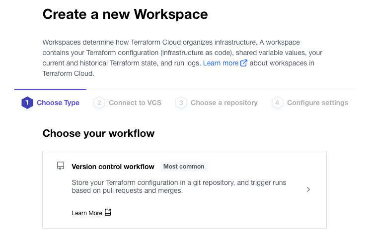
In step 1 of the create a workspace wizard, select the version control workflow:
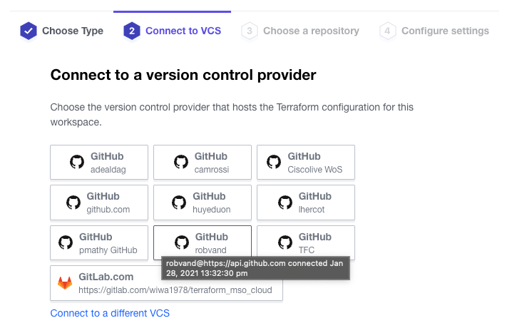
In step 2 of the wizard, select your VCS provider:
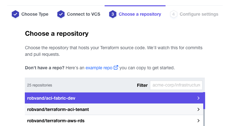
In step 3 of the wizard, select your repository:
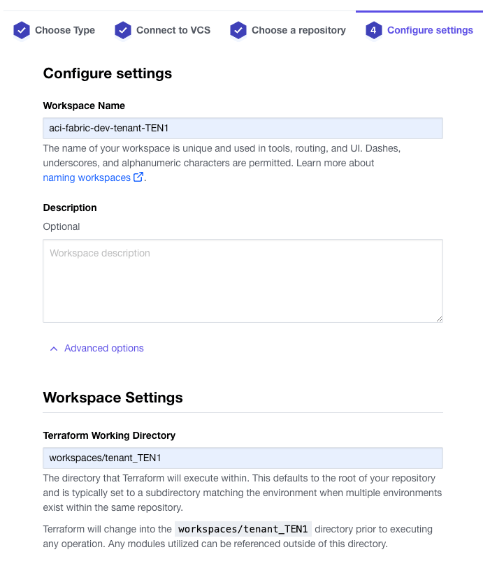
In step 4 of the wizard, provide a new workspace name, expand the advanced options and set the Terraform Working Directory:
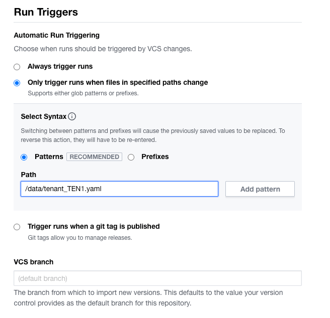
As all plans are part of the same git repository, a run trigger can be configured to only run when files change in specific paths. In this example, the intention is to run the plan within workspaces/tenant_TEN1, when the file data/tenant_TEN1.yaml is updated. You can specificy multiple paths and or files. For more information on VCS and run triggers visit: https://developer.hashicorp.com/terraform/cloud-docs/workspaces/settings/vcs
Note: an alternative option is using git submodules. This would allow the user to store the data and associated plans in different repositories.
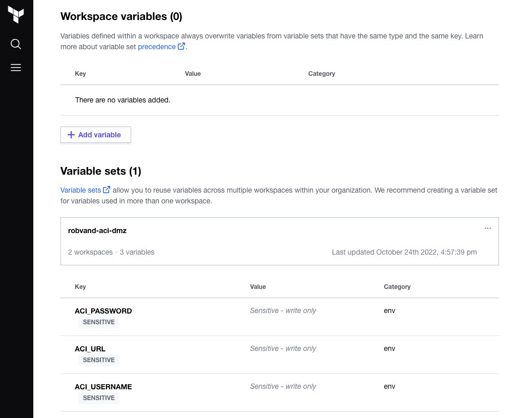
Once you have validated the configuration, proceed with creating the workspace. Add the required workspace variables or use a variable set which allows you to re-use a common set of variables with multiple workspaces:
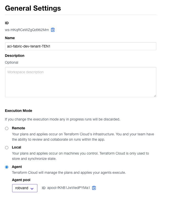
Within the general settings in the workspace change the Execution Mode to Agent and select your pool, followed by saving the settings:
Now that the first workspace has been added you can set up any additional workspaces. The settings for the second workspace are the same with the exception of the following:
- name: aci-fabric-dev-tenant-TEN2
- Terraform Working Directory: workspaces/tenant_TEN2
- Run Trigger pattern: /data/tenant_TEN2.yaml
Note: If the workspace runs on each update in the git repository, verify the Run Trigger pattern in Version Control settings in the workspace.
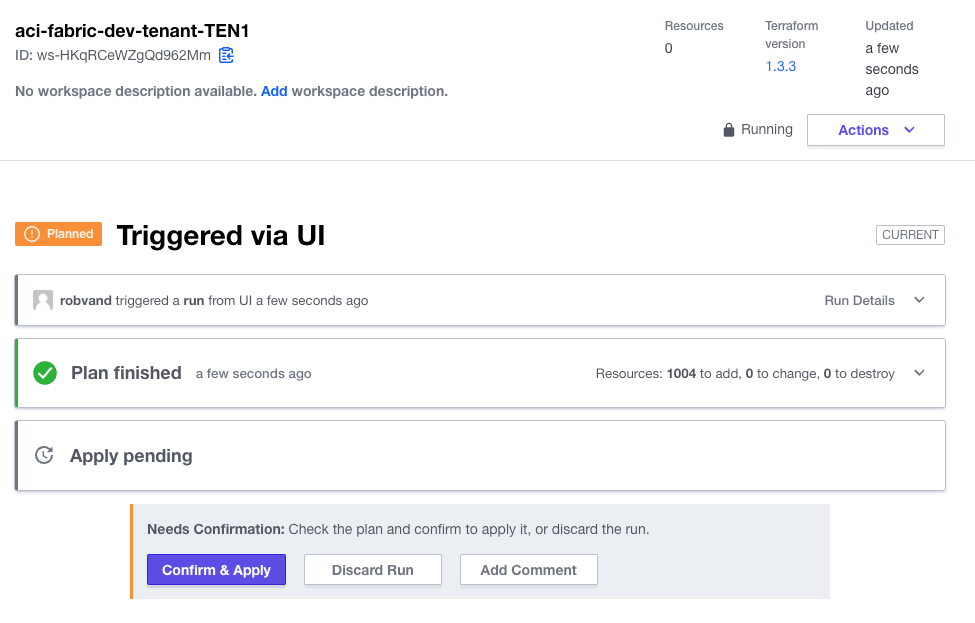
Now that both workspaces are prepared you can initiate the first run via Actions in the workspace section.
Run and apply the plan in each workspace:
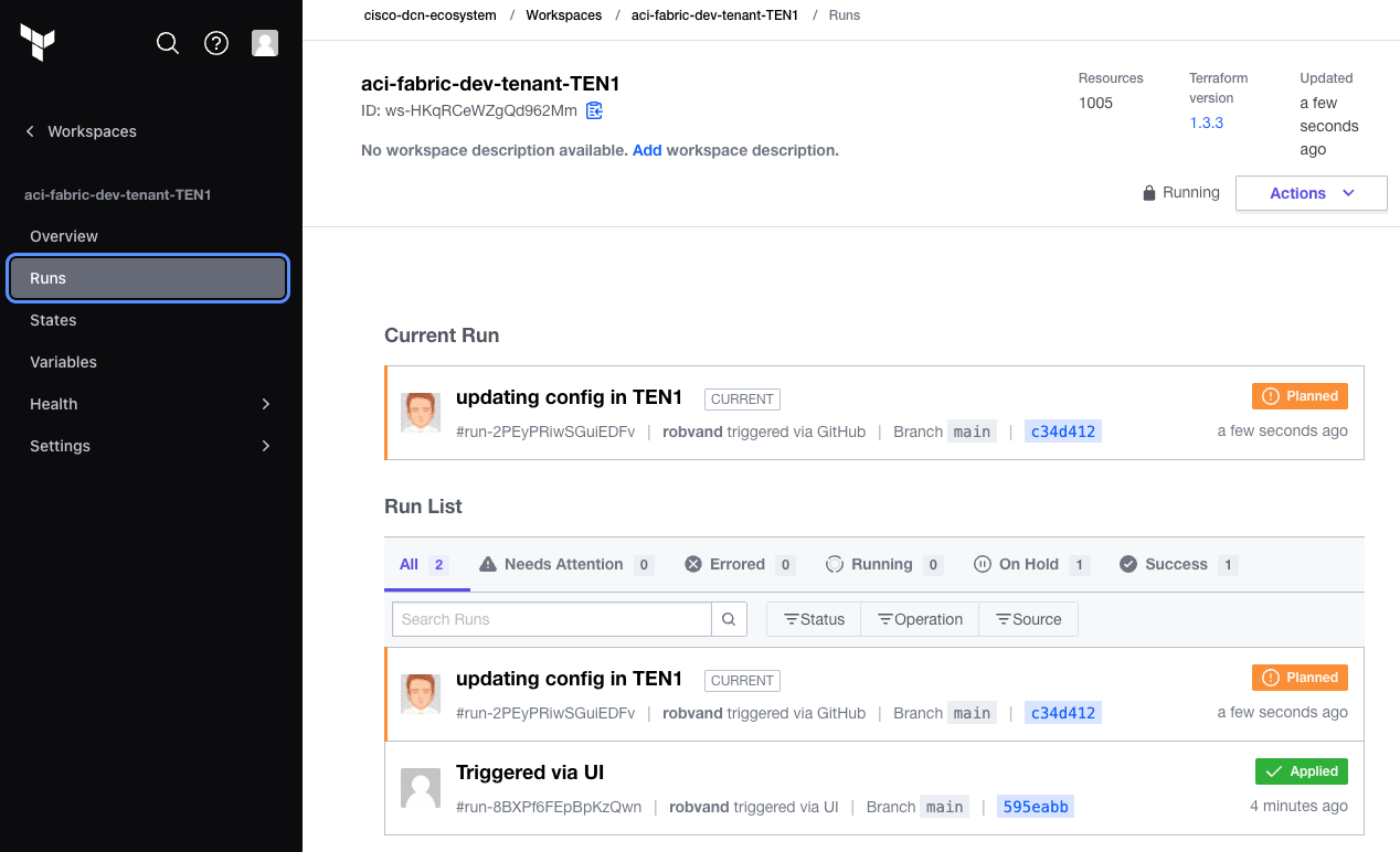
Subsequent changes to the git repository will trigger a run in the workspaces that are watching for specific files to change. An update to data/tenant_TEN1.yaml in the git repository triggered a new run in the aci-fabric-dev-tenant-TEN1 workspace:
Scaling Meraki as Code
Section titled “Scaling Meraki as Code”Meraki environments often grow quickly — a single organization can contain hundreds of networks, each with its own wireless, switching, and security configuration. Keeping all of that in one Terraform state file leads to the same problems described at the top of this page: slow plans, high blast radius, and no parallelism.
A common starting point is one workspace per organization and one workspace per group of 20–30 networks. The 20–30 network threshold is based on the resource density of a typical Meraki network (wireless SSIDs, switch access policies, firewall rules, SD-WAN settings, etc.) and serves as a baseline for keeping plan and apply times predictable. Adjust the group size up or down based on observed times in your environment.
The managed flag
Section titled “The managed flag”The managed flag controls whether Terraform owns the lifecycle of an object or simply looks it up. It is supported at the following levels:
- Organization
- Network
- Organization Adaptive Policy Group
- Organization Policy Object
- Organization Policy Object Group
- More may be added from time to time. Refer to the Data Model for the complete list.
When set to true, Terraform creates, updates, and deletes the object as part of the workspace state. When set to false, the object is treated as pre-existing — Terraform reads its ID via the Meraki API at plan time but will never modify or destroy it.
This allows multiple workspaces to safely reference the same shared resource without conflicting with each other or with the workspace that actually manages it.
Organization
Section titled “Organization”Network workspaces reference the organization they belong to but should never own it. Declare it with managed: false so Terraform looks up the existing organization without modifying or deleting it:
meraki: domains: - name: EU administrator: name: admin organizations: - name: scale_org_1 managed: falseNetwork
Section titled “Network”A network managed by one workspace can be referenced by another (for example, a hub referenced by a spoke workspace). Declare it with managed: false in the referencing workspace:
meraki: domains: - name: EU administrator: name: admin organizations: - name: scale_org_1 managed: false networks: - name: scale_org_1_Hub_Network managed: falseOrganization Adaptive Policy Groups
Section titled “Organization Adaptive Policy Groups”Organization Adaptive Policy Groups defined in one workspace can be referenced by network workspaces that need them (for example, when configuring adaptive policy assignments). Declare them with managed: false in any workspace that should treat them as pre-existing:
meraki: domains: - name: EU administrator: name: admin organizations: - name: scale_org_1 adaptive_policy: groups: - name: Unknown managed: false - name: Infrastructure managed: falseOrganization Policy Objects
Section titled “Organization Policy Objects”Organization Policy Objects (such as CIDR ranges or FQDNs) defined in the organization workspace can be referenced in network workspaces. Set managed: false in any workspace that should read but not own the object:
meraki: domains: - name: EU administrator: name: admin organizations: - name: scale_org_1 policy_objects: - name: global_net_A category: network type: cidr cidr: 10.0.0.0/24 managed: false - name: global_net_B category: network type: cidr cidr: 20.0.0.0/24 managed: falseOrganization Policy Object Groups
Section titled “Organization Policy Object Groups”Organization Policy Object Groups follow the same pattern. A group managed by the organization workspace can be declared with managed: false in any network workspace that references it:
meraki: domains: - name: EU administrator: name: admin organizations: - name: scale_org_1 policy_objects_groups: - name: global_netgroup_A category: NetworkObjectGroup object_names: - global_net_B managed: falseOrganization Adaptive Policy Groups, Organization Policy Objects, and Organization Policy Object Groups are typically defined and owned by the organization workspace. Network workspaces then declare them with managed: false so they can reference the shared objects without taking ownership of them.
Workspace structure
Section titled “Workspace structure”The directory layout below illustrates an organization with networks grouped into batches of 30. Adjust the group size up or down based on observed plan and apply times in your environment:
Directoryscale_org_1
- main.tf
Directorydata
- 01_create_org.nac.yaml
Directoryscale_org_1_Network_1-30
- main.tf
Directorydata
- 02_configure_network.nac.yaml
- 03_add_wireless.nac.yaml
- 04_switch_settings.nac.yaml
- 05_add_firewall_sdwan_settings.nac.yaml
Directoryscale_org_1_Network_31-60
- main.tf
Directorydata
- 02_configure_network.nac.yaml
- …
Directoryscale_org_1_Network_61-90
- main.tf
Directorydata
- 02_configure_network.nac.yaml
- …
Each directory is an independent Terraform workspace with its own state file. The scale_org_1 workspace is the only one that creates and owns the organization. Every network workspace references that organization by name with managed: false.
Organization workspace
Section titled “Organization workspace”The main.tf for the organization workspace is straightforward:
module "meraki" {  source           = "netascode/nac-meraki/meraki"
  yaml_directories = ["data"]}
The corresponding data file sets managed: true and contains all organization-level resources — admins, login security, policy objects, and policy object groups:
meraki: domains: - name: EU administrator: name: admin organizations: - name: scale_org_1 managed: true admins: - name: scale_org_user1 email: scale_org_user1@cisco.com organization_access: full login_security: enforce_password_expiration: false password_expiration_days: 90 enforce_different_passwords: true num_different_passwords: 3 policy_objects: - name: trusted_cidr category: network type: cidr cidr: 10.0.0.0/8 policy_objects_groups: - name: trusted_networks category: NetworkObjectGroup object_names: - trusted_cidrRunning terraform apply in this workspace creates the organization and its organization-level resources only. The resulting state file is small and rarely changes.
Network workspaces
Section titled “Network workspaces”Each network workspace uses the same main.tf structure, pointing to its local data directory:
module "meraki" {  source           = "netascode/nac-meraki/meraki"
  yaml_directories = ["data"]}
The data files inside each network workspace all carry the same organization header, with managed: false to prevent any workspace from attempting to re-create or delete the shared organization:
meraki: domains: - name: EU administrator: name: admin organizations: - name: scale_org_1 managed: false networks: - name: scale_org_1_Network_1 product_types: - appliance - switch - wireless time_zone: Europe/Amsterdam tags: - prod - name: scale_org_1_Network_2 product_types: - appliance - switch - wireless time_zone: Europe/Amsterdam tags: - prod # ... up to ~30 networksAdditional configuration for each group of networks — wireless, switching, firewall — is split across separate files in the same data/ directory. The module merges all *.nac.yaml files automatically, so the full network configuration is assembled from the individual feature files at plan time:
meraki: domains: - name: EU administrator: name: admin organizations: - name: scale_org_1 managed: false networks: - name: scale_org_1_Network_1 wireless: ssids: - name: Corp enabled: true auth_mode: 8021x-radius - name: scale_org_1_Network_2 wireless: ssids: - name: Corp enabled: true auth_mode: 8021x-radiusHow many networks per workspace?
Section titled “How many networks per workspace?”A typical Meraki network with full configuration (wireless SSIDs with RADIUS, switch access policies, firewall rules, and SD-WAN settings) results in roughly 20–25 Terraform resources. At that density, a workspace containing 20–30 networks will have 400–750 resources — a comfortable size that keeps plan and apply times predictable and limits the impact of any single change.
| Networks per workspace | Approx. resources | Typical apply time |
|---|---|---|
| 10 | ~200 | 4–6 min |
| 20 | ~400 | 8–12 min |
| 30 | ~600 | 12–18 min |
| 100 | ~2,000 | 40–50 min |
These figures will vary based on feature density, API rate limits, and network connectivity. Start with 20–30 and adjust based on observed apply times in your environment.
Parallel execution
Section titled “Parallel execution”Because each workspace has its own independent state file, you can run terraform apply across all network workspaces simultaneously. The organization workspace must be applied first to ensure the organization exists before any network workspace references it. After that initial apply, network workspaces have no dependency on each other and can be planned and applied in parallel.
Cross-workspace references
Section titled “Cross-workspace references”Two common scenarios arise when splitting state across workspaces.
Network referencing org-level resources
Section titled “Network referencing org-level resources”If a network workspace needs to reference an org-level resource (such as an Organization Policy Object or Organization Adaptive Policy Group), declare that resource with managed: false directly in the network workspace that needs it. The module will look it up via the Meraki API at plan time without modifying or deleting it.
Keep these org-level references in a dedicated file within the network workspace’s data/ directory — for example 00_remote_org_resources.nac.yaml — to make the cross-workspace dependency explicit and easy to audit:
meraki: domains: - name: EU administrator: name: admin organizations: - name: scale_org_1 managed: false adaptive_policy: groups: - name: Unknown managed: false - name: Infrastructure managed: false policy_objects: - name: global_net_A category: network type: cidr cidr: 10.0.0.0/24 managed: false policy_objects_groups: - name: global_netgroup_A category: NetworkObjectGroup object_names: - global_net_A managed: falseThe locally managed networks in the same workspace can then reference these org-level objects by name in their own data files.
Network referencing another network
Section titled “Network referencing another network”If a network needs to reference another network from a different workspace (for example, a spoke referencing a hub in a VPN topology), declare the remote network with managed: false. The module will look it up via the Meraki API rather than attempting to create it.
The recommended approach is to keep all remote network references in a dedicated file separate from the locally managed networks. This makes cross-workspace dependencies explicit and easy to audit:
Directoryscale_org_1_Network_31-60
- main.tf
Directorydata
- 00_remote_networks.nac.yaml
- 02_configure_network.nac.yaml
- 03_add_wireless.nac.yaml
- 04_switch_settings.nac.yaml
- 05_add_firewall_sdwan_settings.nac.yaml
The 00_remote_networks.nac.yaml file contains only the networks that are managed by other workspaces, all with managed: false:
meraki: domains: - name: EU administrator: name: admin organizations: - name: scale_org_1 managed: false networks: - name: scale_org_1_Hub_Network # managed by the hubs workspace managed: false - name: scale_org_1_Network_5 # managed by the 1-30 workspace managed: falseThe locally managed networks are defined in the regular data files as usual, and can reference the remote networks by name:
meraki: domains: - name: EU administrator: name: admin organizations: - name: scale_org_1 managed: false networks: - name: scale_org_1_Network_35 managed: true product_types: - appliance - switch - wireless time_zone: Europe/Amsterdam - name: scale_org_1_Network_36 managed: true product_types: - appliance - switch - wireless time_zone: Europe/Amsterdam # ... up to ~30 networksmeraki: domains: - name: EU administrator: name: admin organizations: - name: scale_org_1 managed: false networks: - name: scale_org_1_Network_35 appliance: vpn_site_to_site_vpn: mode: spoke hubs: - hub_network_name: scale_org_1_Hub_Network # defined in 00_remote_networks.nac.yaml - name: scale_org_1_Network_36 appliance: vpn_site_to_site_vpn: mode: spoke hubs: - hub_network_name: scale_org_1_Hub_NetworkThe remote networks must already exist in Meraki before this workspace runs terraform plan.