Task 6 - Challenge
So far in this lab, we have:
- Concepts and Tools: We have learned about the Meraki as Code concept, its benefits, and the tools we will be using in this lab.
- Prepare your environment: We have cloned the example repository, set environment variables, and familiarized ourselves with the data model structure.
- Working with Meraki Data Model: We have explored the data model structure, understood how templates and variables are organized, and how to modify them to fit our needs.
- Creating your first Organization: We have created an organization using the Meraki as Code Data Model.
- Configure everything as code: We used Meraki as Code Data Model to deploy multiple features across Meraki Dashboard.
Now it is your turn. In this task, you will write a new YAML data model file from scratch to deploy two new networks into the organization we created earlier. Use what you have learned in the previous tasks — refer back to the YAML examples and the data model reference at netascode.cisco.com as needed.
Write your Data Model YAML with VS Code
Section titled “Write your Data Model YAML with VS Code”Here, you will quickly learn how to use Visual Studio Code / VS Code (IDE) to write your Meraki Data Model much easier and avoid maximum errors before moving on to validate the Data Model.
The Visual Studio code along with YAML Extension provides a comprehensive YAML Language support while you write your Data Model.
Tools Required:
- Any latest version of Visual Studio Code for the Operating system you use. We have Code Server in this lab.
- YAML Extension by Redhat enabled. redhat.vscode-yaml: https://marketplace.visualstudio.com/items?itemName=redhat.vscode-yaml
Enable YAML extension by Redhat on VS Code.
Section titled “Enable YAML extension by Redhat on VS Code.”Open Code Server. You may also try this on VS Code on your local PC.
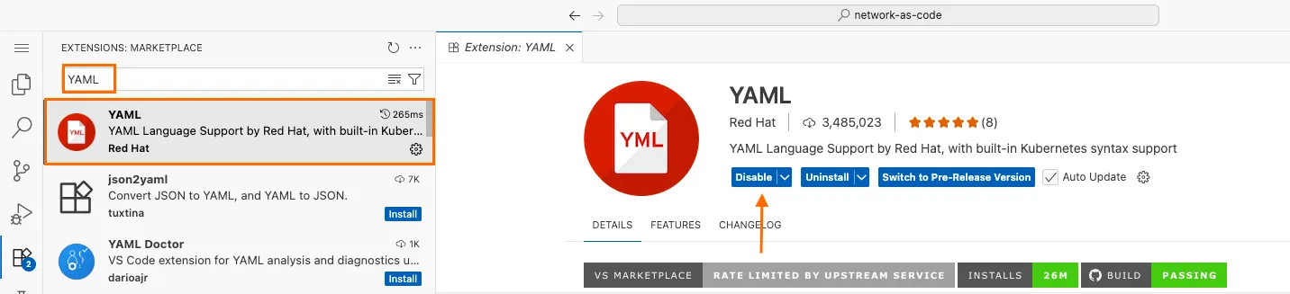
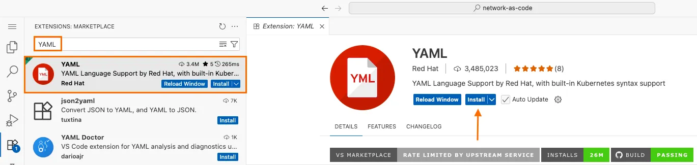
Click on Extensions from the activity bar on the left
Search keyword YAML in the EXTENSIONS bar
a. If you see the Disable or Uninstall buttons, then the Extension is already installed. No further steps required
Write your Meraki Data Model
Section titled “Write your Meraki Data Model”Let us take a look at writing a Data Model for creating a network
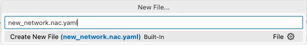
On your Code Server window, browse to File >> New File
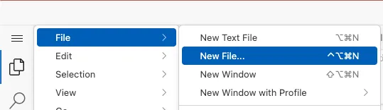
On the New file dialog, enter the file name. For example new_network.nac.yaml Make sure to suffix the file name with .nac.yaml
If the save file dialog pops-up, ensure the filename still ends with .nac.yaml. Do not save this file in the
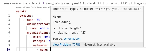
dataorlab-datafolder.Start writing the file with technology name. In this case, write meraki:
Once you hover your mouse pointer over the red Tilde, you will see the YAML extension giving you the possible options that can be placed under meraki. In this case,
domainsandtemplatesare available options. We need to go the path ofdomains.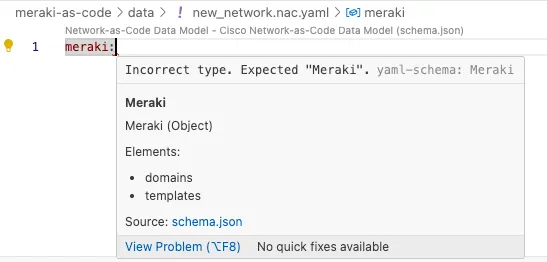
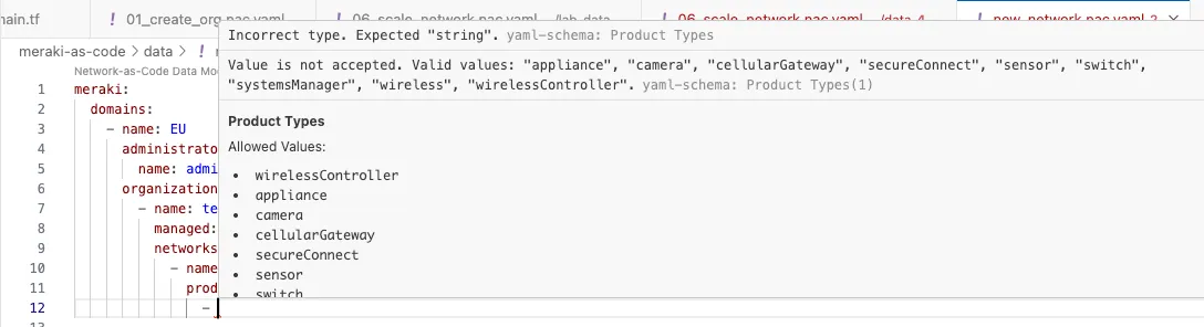
As we want to create Networks, look for the right key from the list and start typing the first few characters of the same. You will see that, you will be able to select the key from the autofill. Keep going until you reach the networks path.
Hint: The network is under
meraki→domains→organizations→networks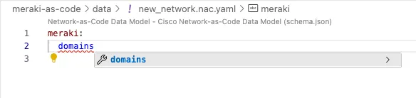
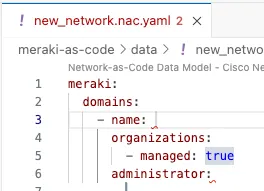
You can use the combinations of auto-fill and the red Tilde (~) highlighter to effectively write the YAML inline with schema.
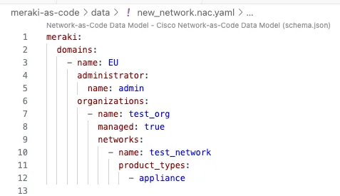
Your Data Model is considered syntactically clean and inline with the schema, when there are no more red Tildes showing up on the file.
Delete this file, if you have placed it under
datafolder. The file was just to practice writing YAML with assistance of VS Code extension.Great !!!
Challenge: Create two networks
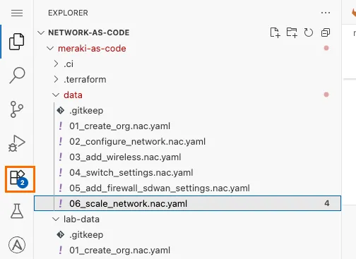
Section titled “Challenge: Create two networks”Create a new YAML file in the data/ folder (e.g., 06_scale_network.nac.yaml) that deploys two networks named Rotterdam-Network-1 and Eindhoven-Network-1 under the existing organization. Both networks should have the same configuration with the following requirements:
Network basics:
- Product types: appliance, switch, and wireless
- Time zone:
Europe/Amsterdam - A descriptive note on the network
- At least one tag applied
Network settings:
- Local status page enabled with authentication (username and password)
- Remote status page enabled
- Secure port disabled
- Named VLANs enabled
SNMP:
- User-based SNMP access
- At least one SNMP user configured with a passphrase
Syslog:
- At least one syslog server configured with a host and port
- Forward the following log roles:
- Switch Event log
- Air Marshal events
- Flows
- URLs
- Wireless Event log
- Appliance Event log
- Start by looking at the
02_configure_network.nac.yamlfile you deployed in Task 5 — it covers network creation, settings, SNMP, and syslog. Use it as a reference for the YAML structure. - The data model hierarchy is:
meraki→domains→organizations→networks. Your new networks go under the same organization you created earlier. - Both networks can be defined as two entries under the
networkslist in a single YAML file. - Refer to the full data model syntax at netascode.cisco.com if you need to check available fields or accepted values.
Solution
Section titled “Solution”The solution is available at file 06_scale_network.nac.yaml in lab_data folder. You may copy this file when deploying the network.
The solution is provided here, so that you can identify how close your data model is to the expected solution.
Step 1: Validate your Configuration
Section titled “Step 1: Validate your Configuration”Once your YAML file is ready, run nac-validate to check for syntax and semantic errors:
cd /home/dcloud/network-as-code/meraki-as-code/nac-validate --non-strict -s schema.yaml -r rules/ data/If you see any validation errors, review the error messages — they will point you to the specific field and file that needs fixing. Correct the issues and re-run validation until it passes cleanly.
Step 2: Plan your changes
Section titled “Step 2: Plan your changes”Use terraform plan to preview what Terraform will create:
terraform planReview the plan output carefully. You should see new resources being created for both Rotterdam-Network-1 and Eindhoven-Network-1 — including the networks themselves, their settings, SNMP configuration, and syslog servers. All resources should be marked with + (create).
Check the plan summary at the bottom:
Plan: 8 to add, 0 to change, 0 to destroy.Step 3: Deploy your Configuration
Section titled “Step 3: Deploy your Configuration”Once you have reviewed the plan and confirmed the changes match your intent, deploy the configuration:
terraform applyTerraform will regenerate the plan and prompt you for confirmation. Review the plan summary and enter yes to proceed.
Do you want to perform these actions?  Terraform will perform the actions described above.  Only 'yes' will be accepted to approve.
  Enter a value: yes
Wait for the deployment to complete. Once done, you should see:
Apply complete! Resources: 8 added, 0 changed, 0 destroyed.Step 4: Verify in Meraki Dashboard
Section titled “Step 4: Verify in Meraki Dashboard”Navigate to your Meraki Dashboard and verify:
- Both
Rotterdam-Network-1andEindhoven-Network-1appear under your organization - Each network has appliance, switch, and wireless product types
- Network settings show the local status page enabled with authentication
- SNMP is configured with user-based access
- Syslog servers are configured with the correct host, port, and log roles
Congratulations — you have successfully written and deployed a Meraki as Code data model from scratch!